
Project Number: 3106
Continuous A Frame Coil Drying Conveyor Oven for Post Leak-Test Water Removal


Overview
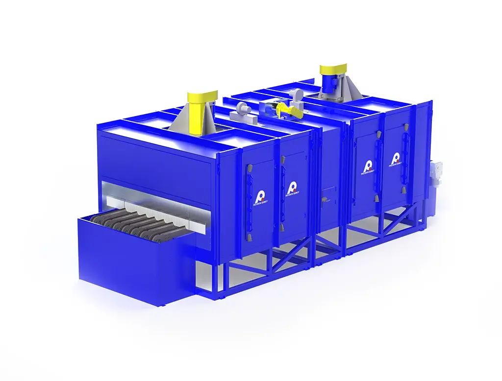
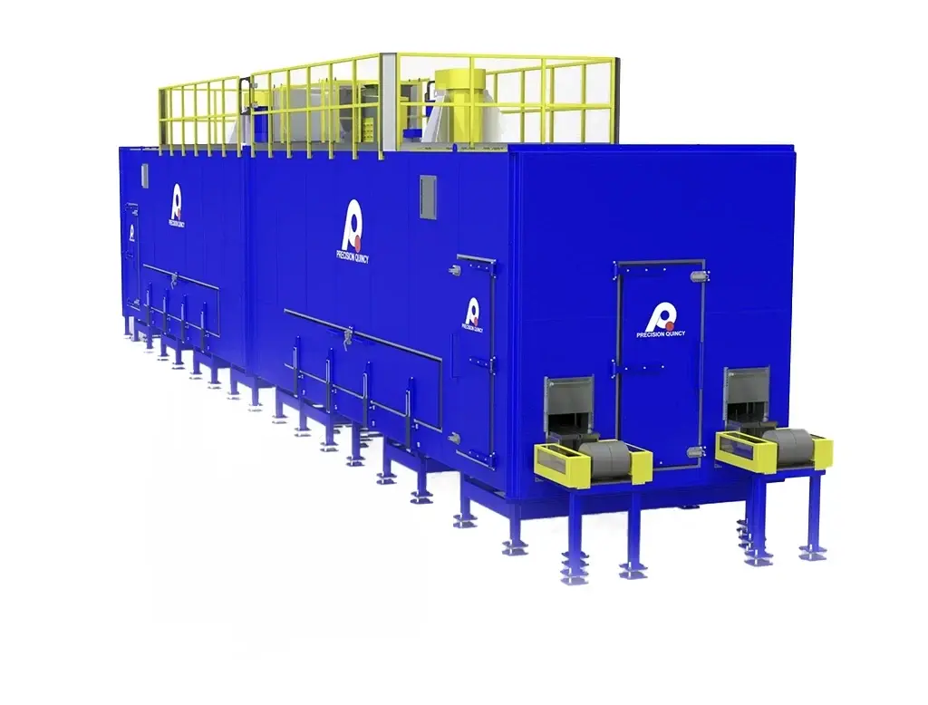
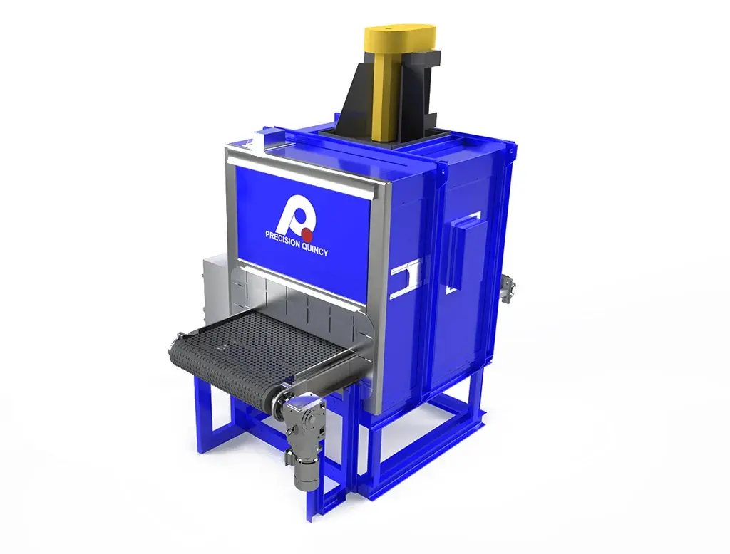
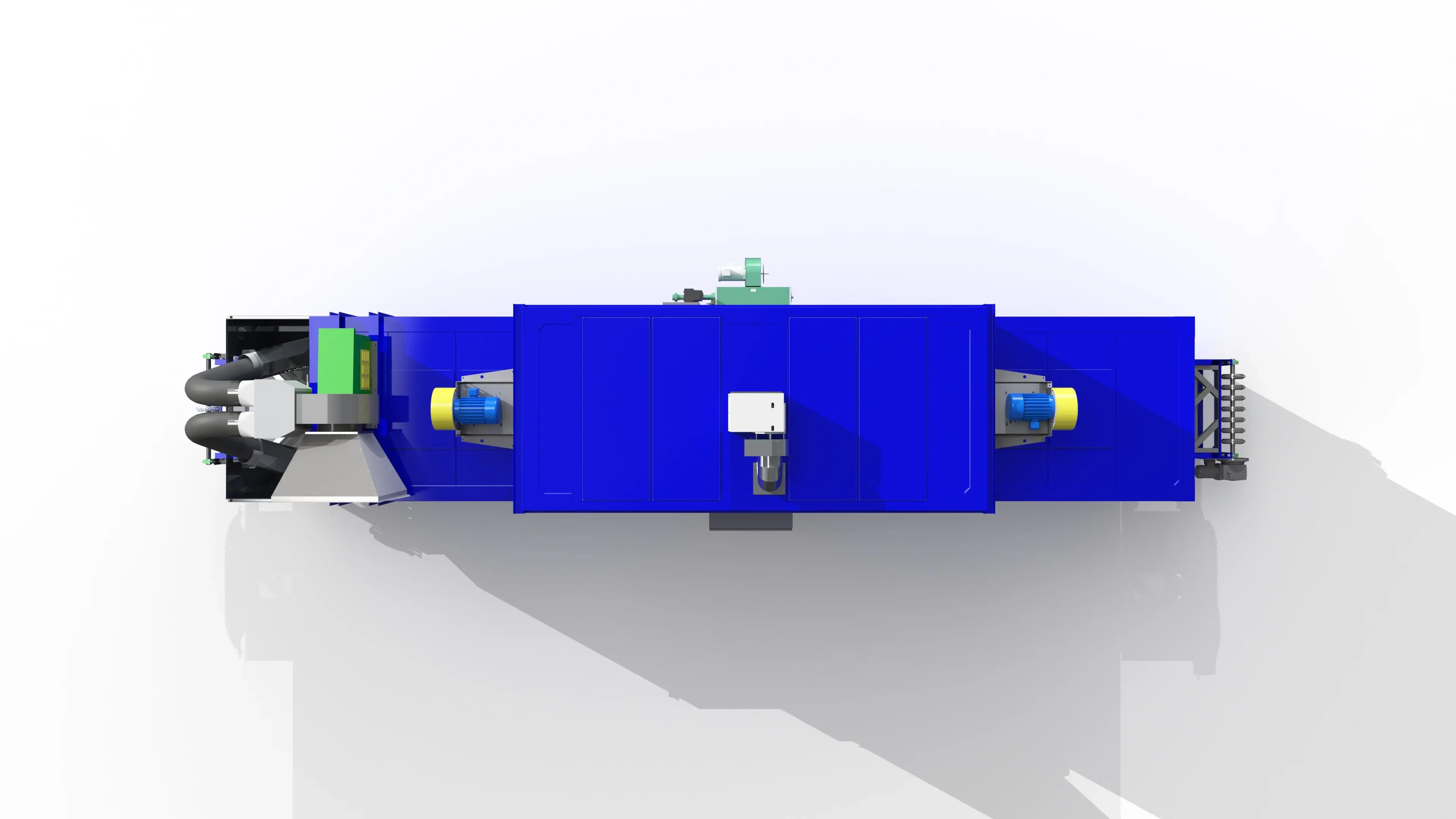
Precision Quincy engineered a compact, high-reliability coil drying conveyor oven for a major manufacturer of residential and commercial HVAC equipment -- purpose-built to dry A-frame aluminum air-conditioning coils immediately after a water-dunk leak test. The system removes residual moisture from within the fin pack so coils can move cleanly into downstream manufacturing without water carryover, while protecting the product with a strict 250F maximum process limit.
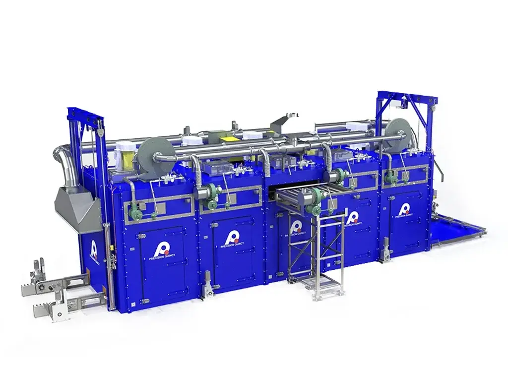
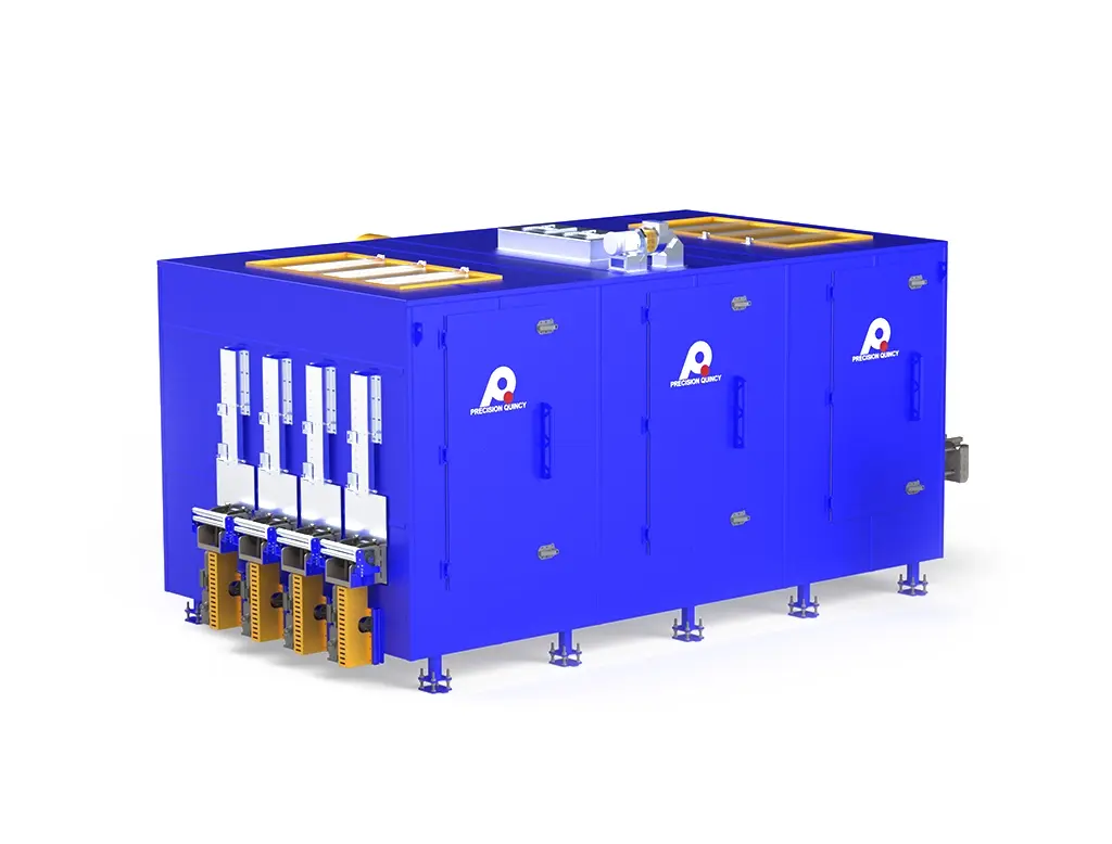
Using customer-supplied coils, Precision Quincy validated the process in its test lab and translated the results into a single-pass, cost-conscious architecture that fits the customer's tight line envelope (485.8 in overall length, including upstream blow-off). A high-energy air knife (8,000 FPM; 3,700 CFM) strips bulk water before the heated section, enabling efficient evaporation of the remaining moisture load. Inside the oven, a double T-duct delivers side-impingement through 4 in x 4 in nozzle arrays at 4,000 FPM +/-10%, driven by two 24-inch PLR recirculation fans (12,185 CFM each) and stabilized with a fixed 2,100 CFM roof exhaust for moisture removal.
The drying process operates at a nominal 225F setpoint (250F max) with +/-10F uniformity, supplied by a SELAS PH200 natural gas burner rated at 2.0 MMBtu/hr. To align with customer cost targets, the system eliminates a PLC in favor of simplified controls -- PowerFlex 4M VFDs with rotary speed control, airflow proving switches, and redundant high-temperature limits -- while preserving durability through 304 stainless ducting and a heavy-duty stainless flat wire belt conveyor. The completed system was fully tested at Precision Quincy prior to shipment.
A major manufacturer of residential and commercial HVAC equipment required a continuous conveyor drying system to remove residual water from A-frame aluminum air-conditioning coils immediately after a water-dunk leak test. Coils are brazed/welded to be airtight for refrigerant service, verified by submerging assemblies and checking for bubbles. After leak testing, coils must be dried thoroughly before proceeding to the next manufacturing step.
APPLICATION & PRODUCT TYPE
- Product: A-frame aluminum air-conditioning coil assemblies.
- Process: Post-leak-test drying in a continuous conveyor oven to remove residual water before downstream manufacturing.
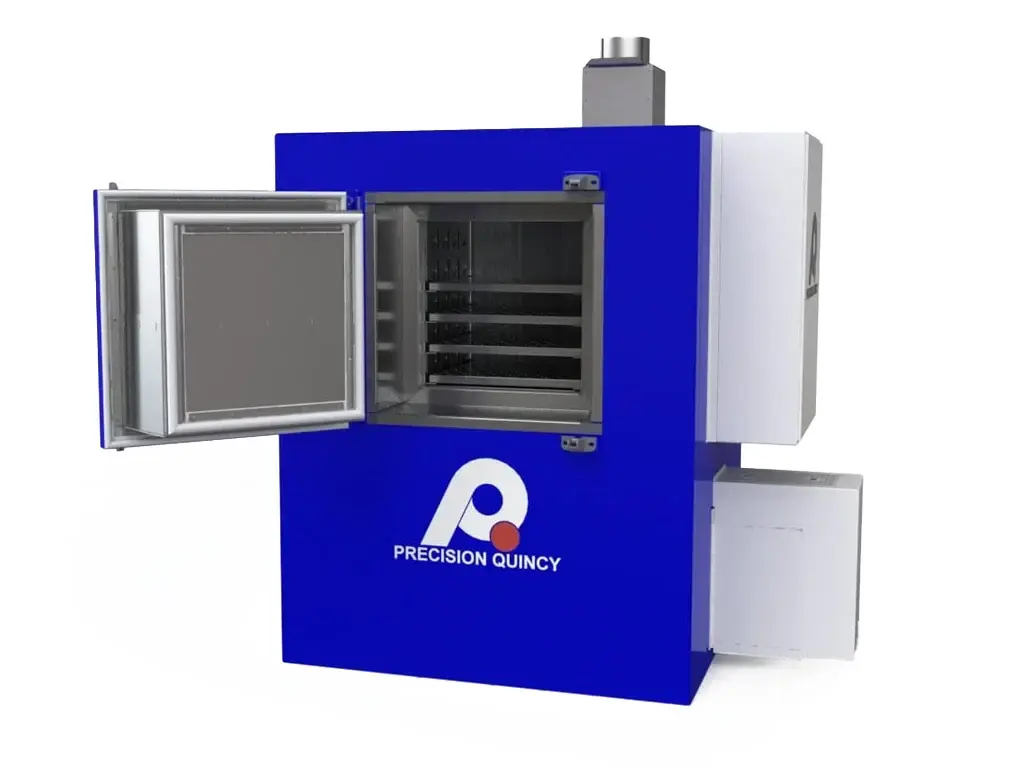
- Orientation: Coils conveyed so the A-shape is visible from the end of the oven, exposing fin geometry for effective moisture removal.
- Path: Single-pass through the drying system on a flat wire belt conveyor.
THROUGHPUT REQUIREMENT
- Required production rate: 1 coil per minute.
- Dwell time: 10 minutes.
PRODUCT ENVELOPE & LOAD
- Coil dimensions (max): 26.5 in W × 33 in H × 26 in L (L in direction of travel).
- Maximum coil weight: 50 lb. Maximum retained water load: 16 lb per coil. Maximum combined weight: 66 lb per coil.
DEFINITION OF "DRY" (ACCEPTANCE CRITERIA)
- Visual: No visible water droplets remaining on coil.
- Weight: Coil weight consistent with expected dry coil weight (no measurable retained water).
PRODUCT PROTECTION & SITE CONSTRAINTS
- Maximum allowable process temperature: 250°F max.
- Overall system length: approximately 485 in (including upstream blow-off section). Ceiling height: not limiting.
- Energy-efficiency: upstream air knife removes bulk water before heated drying to reduce evaporation load.
These thermal process requirements were developed through in-house testing at Precision Quincy using customer-provided A-frame coils. Testing established the minimum blow-off, airflow, temperature, and heat input needed to consistently meet the customer's dryness acceptance criteria (visual + weight) at the required throughput within the available footprint.
TEMPERATURE REQUIREMENTS
- Nominal operating temperature: 225°F. Maximum allowable: 250°F (product protection limit).
- Temperature uniformity: ±10°F from setpoint at nozzle discharge.
THROUGHPUT / DWELL TIME BASIS
- Production rate: 1 coil per minute; dwell time: 10 minutes.
- Nominal conveyor speed: 2.5 ft/min; adjustable range: 1.5–4.5 ft/min.
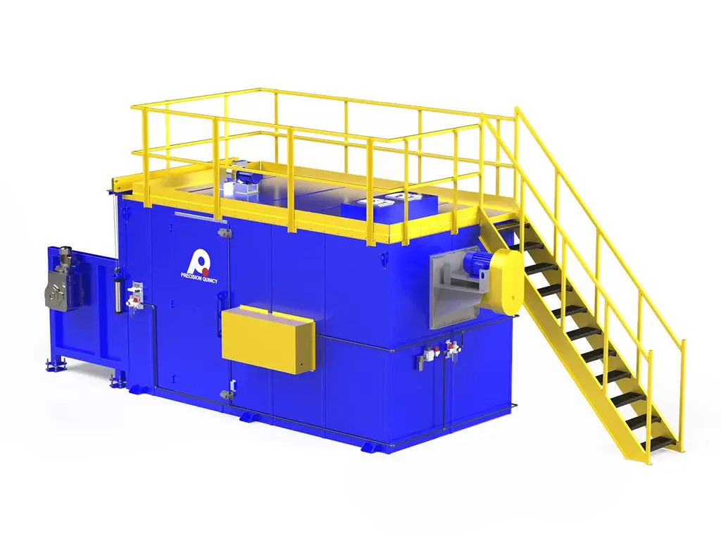
UPSTREAM BLOW-OFF (AIR KNIFE) REQUIREMENT
- Air knife velocity: 8,000 FPM; supply airflow: 3,700 CFM.
- Water removal efficiency: ≥95% of incoming retained water removed upstream (testing-based).
- Purpose: remove bulk water upstream so the heated section evaporates only the remaining moisture load.
DRYING AIRFLOW DELIVERY (IMPINGEMENT)
- Nozzle discharge velocity: 4,000 FPM ±10%; nozzle geometry: 4 in × 4 in square nozzles.
- Airflow direction: perpendicular to the coil face (side impingement). Total recirculation: 24,370 ACFM.
- Exhaust rate: 2,100 CFM fixed (moisture removal + combustion products).
HEAT INPUT & COMPLIANCE
- Required heat power: 2,000,000 BTU/hr; burner turndown: 20:1 minimum required, 30:1 selected.
- NFPA 86 Class A (gas-fired system). Low-NOx not required.
To deliver the thermal process requirements (which deliver the customer process requirements), Precision Quincy settled on the following equipment concept and architecture.
OVERALL CONCEPT
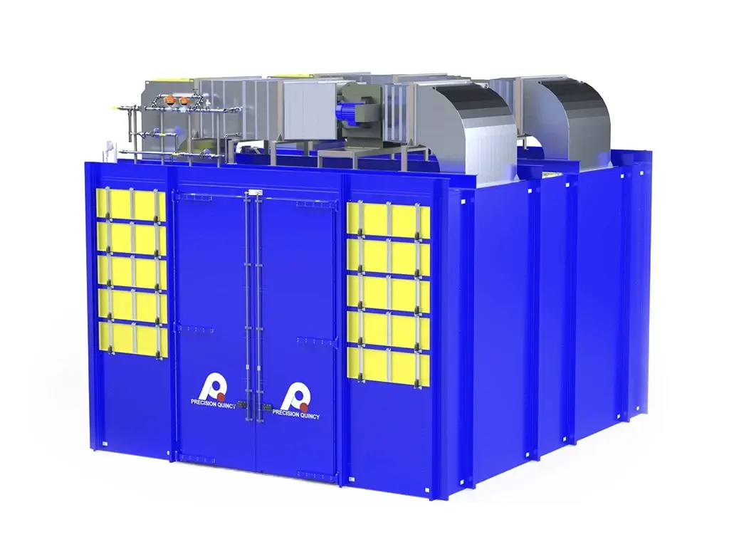
- Single control zone drying oven with dual recirculation fans fed by one burner.
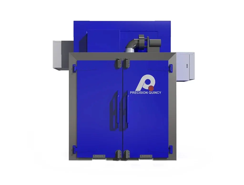
- Top-mounted heat chamber with top-mounted recirculation fans; side-mounted SELAS PH200 burner; roof-mounted exhaust.
AIRFLOW / DUCTING ARCHITECTURE (DOUBLE "T" DUCT)
- Double T-style ductwork distributes conditioned air to both sides of the work chamber.
- Impingement nozzles deliver 4,000 FPM perpendicular to the coil face. Return air flows back to the heat chamber for re-heating.
HEATING & COMBUSTION
- Burner: SELAS PH200 natural gas-fired, 2.0 MMBtu/hr, 30:1 turndown.
- Burner safety system: Karl Dungs-based.
RECIRCULATION FAN SYSTEM
- Two 24-inch PLR fans; 12,185 CFM each (24,370 CFM total); 10 HP each, VFD-controlled (Allen-Bradley PowerFlex 4M).
CONVEYOR / HANDLING CONCEPT
- Belt: SSI804 stainless steel 1×1 flat wire belt.
- Drive: Helical bevel gearbox, VFD-controlled with rotary potentiometer speed control.
- Cantilever take-up; unpowered roller return; stainless steel herringbone slider bed.
- Conveyor capacity: ~1,188 lb (18 coils × 66 lb/coil).
CONTROLS ARCHITECTURE (COST-REDUCED)
- No PLC (customer cost-savings requirement); Allen-Bradley PowerFlex 4M VFDs, rotary potentiometer speed control.
- Airflow proving switches on each fan, exhauster, and burner. Dual high limits + work-chamber TC high limit. Remotely mounted control cabinet.
CONSTRUCTION / SHELL ARCHITECTURE
- Panelized oven with structural steel reinforcement; 4 in walls; 18-gauge aluminized steel interior/exterior.
- 304 stainless steel ductwork (longevity in wet/drying environment); removable explosion relief plugs in heat-chamber roof.
- Exterior finish: two-part epoxy, PQ Blue. Shipped in one piece; only the exhauster removed for shipment.
| OVEN CONFIGURATION | |
|---|---|
| Type | Continuous conveyor, one-zone, single-pass, horizontal airflow with side-impingement drying; includes air-knife blow-off upstream |
| Heated Zone Length | 300 in |
| Inlet / Outlet Vestibules | 18 in each end |
| Conveyor Width | 36 in |
| Conveyor Type | Heavy-duty flat wire belt |
| Overall Dimensions | 79.2 in W × 485.8 in L × 154.5 in H |
| Shipping | Shipped in one piece; exhauster removed for shipment |
| Explosion Relief | Removable explosion relief plugs in heat-chamber roof |
| THERMAL HEAT POWER SYSTEM | |
|---|---|
| Operating Temperature | 225°F |
| Maximum Temperature | 250°F max (product protection limit) |
| Temperature Uniformity | ±10°F from setpoint at nozzle discharge |
| Heating Zones | 1 |
| Heat Source | SELAS PH200 natural gas-fired burner (dry-fired, non-low-NOx) |
| Heat Power | 2,000,000 BTU/hr |
| Burner Turndown | 20:1 required (testing-based); 30:1 selected |
| Burner Safety Hardware | Karl Dungs-based safety system |
| BLOW-OFF AND DRYING AIRFLOW SYSTEM | |
|---|---|
| Air Knife Velocity | 8,000 FPM |
| Air Knife Supply Airflow | 3,700 CFM |
| Air Knife Water Removal | ≥95% of incoming retained water removed upstream (testing-based) |
| Impingement Airflow Pattern | Side-nozzle impingement; airflow perpendicular to coil face |
| Nozzle Geometry | 4 in × 4 in square nozzles |
| Nozzle Discharge Velocity | 4,000 FPM ±10% |
| Recirculation Airflow (Total) | 24,370 ACFM |
| Recirculation Fans | (2) 24-inch PLR fans, 12,185 CFM each |
| Fan Motors | 10 HP each (20 HP total), VFD-controlled |
| EXHAUST SYSTEM | |
|---|---|
| Fan Type | PQ15 roof-mounted exhaust |
| Exhaust Rate | 2,100 CFM (fixed / non-modulated) |
| Purpose | Removes evaporated moisture + products of combustion |
| CONVEYOR / HANDLING SYSTEM | |
|---|---|
| Belt | SSI804 stainless steel 1×1 flat wire belt |
| Drive | Helical bevel gearbox, VFD-controlled |
| Speed Control Interface | Rotary potentiometer (no PLC) |
| Speed Range | 1.5–4.5 ft/min |
| Nominal Speed | 2.5 ft/min |
| Take-Up | Cantilever take-up |
| Return | Unpowered rollers |
| Slider Bed | Stainless steel (herringbone pattern) |
| Conveyor Capacity | ~1,188 lb evenly distributed (18 coils × 66 lb/coil) |
| CONSTRUCTION MATERIALS / FINISH | |
|---|---|
| Primary Structure | Structural steel reinforced, panelized construction |
| Wall Thickness | 4 in |
| Interior / Exterior Skin | 18-gauge aluminized steel |
| Ductwork | 304 stainless steel (longevity in wet/drying environment) |
| Paint | Two-part epoxy, PQ Blue |
| SAFETY & COMPLIANCE | |
|---|---|
| NFPA 86 Classification | Class A (gas-fired system) |
| Explosion Relief | Roof-mounted removable explosion relief plugs |
| Airflow Proving | (1) airflow switch on each recirculation fan, exhauster, and burner |
| High Temperature Limits | Dual high limits (one per fan/heat chamber circuit) + separate work-chamber TC high limit |
| Code Compliance | NFPA 86 and OSHA |
| CONTROLS & ELECTRICAL | |
|---|---|
| PLC | None (cost-reduced architecture) |
| VFDs | Allen-Bradley PowerFlex 4M |
| Control Cabinet Location | Remotely mounted |
| PROCESS SPECIFICATIONS | |
|---|---|
| Parts Processed | A-frame aluminum HVAC coils (post dunk leak test) |
| Process | Blow-off + heated drying (water removal) |
| VOCs | None |
| Testing / FAT | Equipment fully tested at Precision Quincy prior to shipment |
